- 您现在的位置:买卖IC网 > Sheet目录1994 > DS3232MZ+ (Maxim Integrated Products)IC RTC W/SRAM I2C 8SOIC
DS3232M
±5ppm, I2C Real-Time Clock with SRAM
11
Maxim Integrated
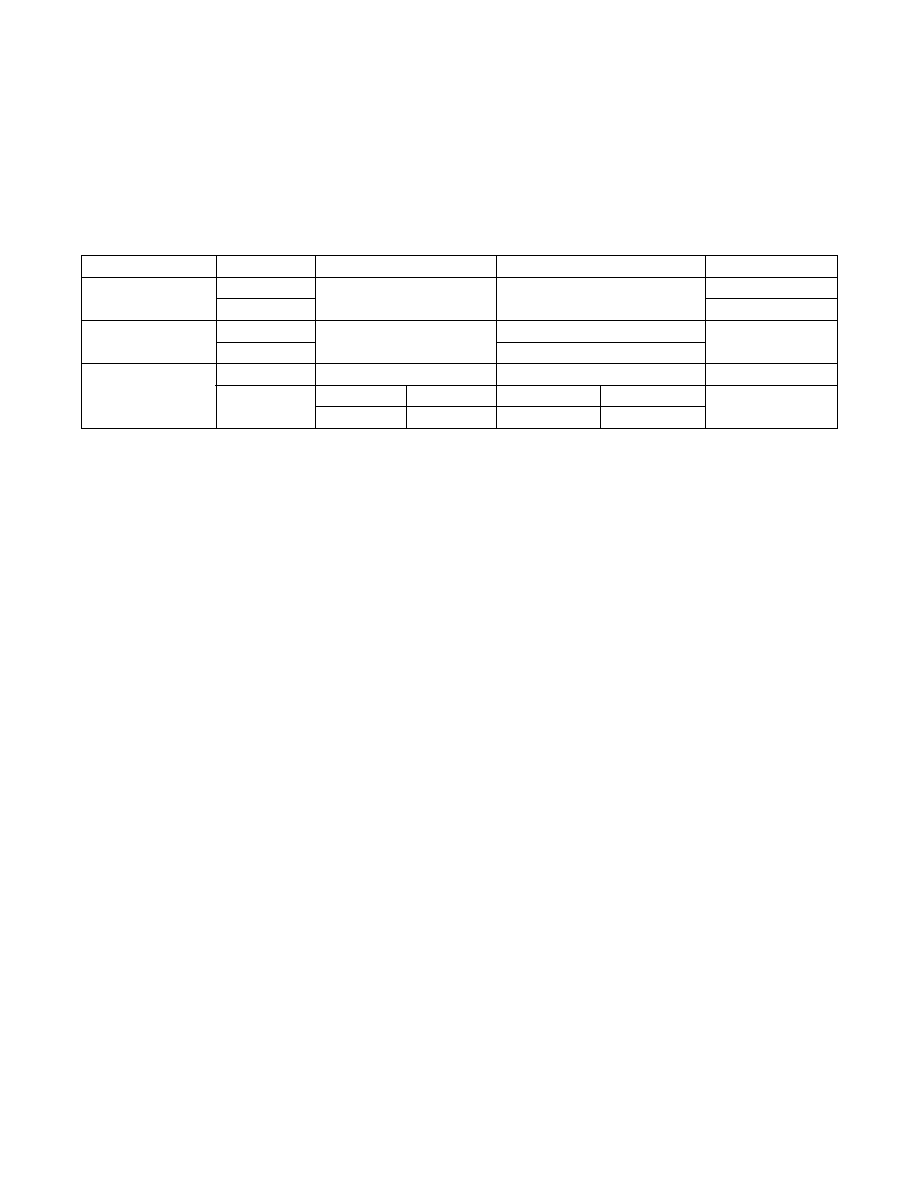
Table 1. Power Control
To preserve the battery, the first time VBAT is applied
to the device the oscillator does not start up until VCC
exceeds VPF or until a valid I2C address is written to
the device. Typical oscillator startup time is less than
1s. Approximately 2s after VCC is applied, or a valid
I2C address is written, the device makes a temperature
measurement and applies the calculated correction to
the oscillator. Once the oscillator is running, it continues
to run as long as a valid power source is available (VCC
or VBAT), and the device continues to measure the tem-
perature and correct the oscillator frequency. On the first
application of VCC power, or (if VBAT powered) when a
valid I2C address is written to the device, the time and
date registers are reset to 01/01/00 01 00:00:00 (DD/MM/
YY DOW HH:MM:SS).
VBAT Operation
There are several modes of operation that affect the
amount of VBAT current that is drawn. While the device
is powered by VBAT and the serial interface is active,
the active battery current IBATA is drawn. When the
serial interface is inactive, the timekeeping current IBATT
(which includes the averaged temperature-conversion
current IBATTC) is used. The temperature-conversion
current IBATTC is specified since the system must be
able to support the periodic higher current pulse and
still maintain a valid voltage level. The data-retention
current IBATDR is the current drawn by the device when
the oscillator is stopped (EOSC = 1). This mode can be
used to minimize battery requirements for periods when
maintaining time and date information is not necessary,
e.g., while the end system is waiting to be shipped to a
customer.
Pushbutton Reset Function
The device provides for a pushbutton switch to be con-
nected to the RST input/output pin. When the device is
not in a reset cycle, it continuously monitors RST for a
low-going edge. If an edge transition is detected, the
device debounces the switch by pulling RST low. After
the internal timer has expired (PBDB), the device con-
tinues to monitor the RST line. If the line is still low, the
device continuously monitors the line looking for a rising
edge. Upon detecting release, the device forces RST
low and holds it low for tRST. RST is also used to indi-
cate a power-fail condition. When VCC is lower than VPF,
an internal power-fail signal is generated, which forces
RST low. When VCC returns to a level above VPF, RST
is held low for approximately 250ms (tREC) to allow the
power supply to stabilize. If the oscillator is not running
when VCC is applied, tREC is bypassed and RST imme-
diately goes high. Assertion of the RST output, whether
by pushbutton or power-fail detection, does not affect
the device’s internal operation. RST output operation and
pushbutton monitoring are only available if VCC power is
available.
CONFIGURATION
CONDITION
I/O ACTIVE
I/O INACTIVE
RST
VCC Only
(Figure 4)
VCC > VPF
ICCA
ICCS
Inactive (High)
VCC < VPF
Active (Low)
VBAT Only
(Figure 5)
EOSC = 0
IBATA
IBATT
Disabled (Low)
EOSC = 1
IBATDR
Dual Supply
(Figure 6)
VCC > VPF
ICCA
ICCS
Inactive (High)
VCC < VPF
VCC > VBAT
ICCA
VCC > VBAT
ICCS
Active (Low)
VCC < VBAT
IBATA
VCC < VBAT
IBATT
发布紧急采购,3分钟左右您将得到回复。
相关PDF资料
DS3232SN#T&R
IC RTC W/TCXO 20-SOIC
DS3234S#
IC RTC W/TCXO 20-SOIC
DS32C35-33#T&R
IC RTC ACCURATE I2C 3.3V 20-SOIC
DS3911T+
IC DAC 10BIT I2C QUAD 14TDFN
DS4000KI/WBGA
IC OSC TCXO 19.44MHZ 24-BGA
DS4026S+WCN
IC OSC TCXO 25MHZ 16-SOIC
DS4100HW+
IC OSC CLOCK 100MHZ 10LCCC
DS4266P+
IC OSC CLOCK 266MHZ 10-LCCC
相关代理商/技术参数
DS3232MZ+TRL
功能描述:实时时钟 RTC/TCMO/MEMS RoHS:否 制造商:Microchip Technology 功能:Clock, Calendar. Alarm RTC 总线接口:I2C 日期格式:DW:DM:M:Y 时间格式:HH:MM:SS RTC 存储容量:64 B 电源电压-最大:5.5 V 电源电压-最小:1.8 V 最大工作温度:+ 85 C 最小工作温度: 安装风格:Through Hole 封装 / 箱体:PDIP-8 封装:Tube
DS3232N
制造商:MAXIM 制造商全称:Maxim Integrated Products 功能描述:Extremely Accurate I2C RTC with Integrated Crystal and SRAM
DS3232S
制造商:Maxim Integrated Products 功能描述:Extremely Accurate I2C RTC
DS3232S-
制造商:MAXIM 制造商全称:Maxim Integrated Products 功能描述:Extremely Accurate I2C RTC with Integrated Crystal and SRAM
DS3232S#
功能描述:实时时钟 Integrated RTC/TCXO/Crystal RoHS:否 制造商:Microchip Technology 功能:Clock, Calendar. Alarm RTC 总线接口:I2C 日期格式:DW:DM:M:Y 时间格式:HH:MM:SS RTC 存储容量:64 B 电源电压-最大:5.5 V 电源电压-最小:1.8 V 最大工作温度:+ 85 C 最小工作温度: 安装风格:Through Hole 封装 / 箱体:PDIP-8 封装:Tube
DS3232S#T&R
制造商:Maxim Integrated Products 功能描述:EXTREMELY ACCURATE I2C RTC 20SOIC W - Tape and Reel 制造商:Maxim Integrated Products 功能描述:DS3232 3V 20P SOIC 制造商:Maxim Integrated Products 功能描述:IC RTC W/TCXO 20-SOIC
DS3232S#T&R
功能描述:实时时钟 Integrated RTC/TCXO/Crystal RoHS:否 制造商:Microchip Technology 功能:Clock, Calendar. Alarm RTC 总线接口:I2C 日期格式:DW:DM:M:Y 时间格式:HH:MM:SS RTC 存储容量:64 B 电源电压-最大:5.5 V 电源电压-最小:1.8 V 最大工作温度:+ 85 C 最小工作温度: 安装风格:Through Hole 封装 / 箱体:PDIP-8 封装:Tube
DS3232SN
制造商:Maxim Integrated Products 功能描述:Extremely Accurate I2C RTC